Around the end of May 2005, one of ALDI's promotional sale items was a 32" Tevion-branded LCD TV, made by Medion of Germany (Medion also have a UK Site). The Medion model number is MD30132.
Since the price was very competitive (around £750 in the UK or €1100 for Irish customers), this naturally attracted a lot of interest. In fact, I bought one myself. Although on balance, the screen is still good value for money, a number of customers became irate because of false or misleading claims made for the screen's capabilities in the promotional literature and packing.
The original AVForums thread discussing the screen and its features can be found here - be warned, it is very long!.
A second thread summarises all known problems, and available resolutions (if any), and is here.
There is also a lengthy German thread at the German Hi-fi forum here (or translated via Google here).
Aldi and Medion have addressed some of these concerns with a firmware update. Currently, this is only available by either sending your 32" screen back to Medion HQ for a warranty upgrade (a considerable undertaking, especially if you've ditched the original packaging), or more recently, arranging for a Medion engineer to call out and update it on site.
As most customers will have noticed, there is a mysterious 8-pin RJ45 socket at the rear of the TV labelled "serial". Medion confirmed on the phone to me that this is used for firmware upgrades. Since no additional information on the use of this port has been forthcoming, I decided to do a little investigation to see what was needed to bring to life. What I've discovered so far is recorded here, for the benefit of anyone else doing similar work.
Why do I want to do this? Mainly to try and discover what would be involved in doing a local firmware update myself, without the need for an engineer to call out and/or return my unit back to Medion -- since I am based in Dublin, both options are likely to be expensive propositions. (And who knows ... it may even be possible to add some additional features to the firmware with a little ingenuity.)
DISCLAIMER: THE INFORMATION HERE IS FOR INFORMATIONAL PURPOSES ONLY; USING IT MAY VOID YOUR WARRANTY. BY CONTINUING TO READ THIS PAGE, YOU AGREE THAT I WILL NOT BE HELD LIABLE FOR ANY DAMAGE THAT MAY RESULT FROM YOUR USING THIS INFORMATION IN ANY WAY WHATSOEVER. (UNLESS YOU ARE FAMILIAR WITH CIRCUITS AND ELECTRONICS, YOU ALMOST CERTAINLY SHOULD NOT BE MESSING WITH THIS STUFF.)
(Sorry for the shouting, but you can't be too careful these days!)
The first step was to open up the Tevion to see what was inside. To do this, I put the screen face down on a flat table (with the base sticking over the edge), then used a Torx T-10 screwdriver to remove the security screws; there are quite a few of them, so make sure you get them all. Then remove the metal baseplate using a Torx T-15 screwdriver (again, quite a few screws).
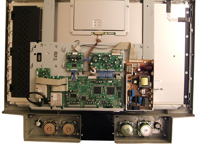
With all of the screws removed, you can easily remove the plastic backpanel (note the way the power switch pivots as the cover passes over it; you need to do this in reverse when closing the screen later on, otherwise the cover jams.) With the cover removed, the screen looks like this:
The important bit is the medium sized circuit board with all the ribbon cables attached, centred above the two pairs of speakers. This contains all the A/V input connectors, along with the host CPU, Flash & RAM, and DSP chips that drive the video display. Here's a close-up (click for a high-resolution version if you're interested in the smaller components):
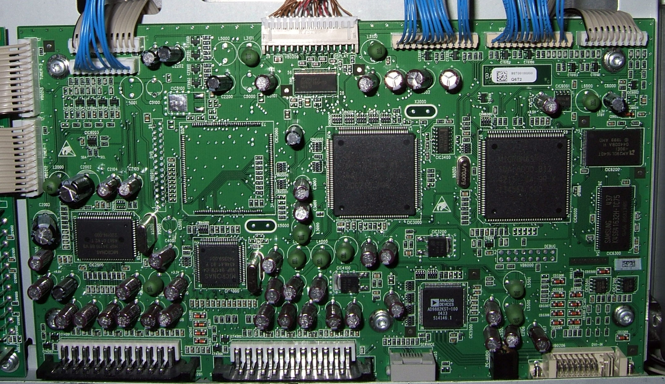
I've labelled the important chips, since it's a bit hard to read the markings on the packaging. You can also see the RJ45 serial connector in the bottom centre of the picture (it's the light grey rectangle just underneath the AD9882 chip).
Here's what the chips do (note that Micronas require you to register with their site before you can retrieve any datasheets):
| Chip | Description |
| Micronas SDA6000 | Main CPU and GUI display engine; based on the popular Infineon C166 16-bit embedded processor |
| Micronas DPS9450A | Display processor and scaler with HDTV and PC input (datasheet is for the newer DPS9455B - 9450A info no longer available) |
| Micronas VSP9417B | Color Decoder and Scan-Rate Converter |
| Micronas MSP3411G | Multi-standard Sound Processor |
| AMD AM29DL164T | AMD 2 MB flash memory |
| Analog Devices AD9882 | SVGA analogue to digital conversion chip (note that default datasheet is for the newer AD9882A part; however, information about the older part is available under "More Datasheets" on the Analog Devices website). |
| Samsung K4S641632H | Samsung 8 MB SDRAM |
| DS90C385MTD | National Semiconductor 24-bit flat panel display controller |
| 24LC04B | 4 Kbit I2C EEPROM (for digital monitors?) |
| 24LC21A | 1 Kbit I2C EEPROM (for analogue monitors) |
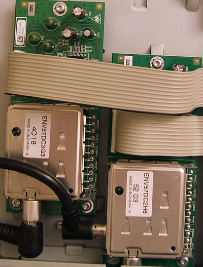
(In case you're interested, this is what the dual tuner module looks like.)
With the aid of a continuity tester, I was able to trace the pins on the RJ45 connector. All the data pins are routed to the SDA6000, and they look like this:
|
RJ45 Pin |
SDA6000 Pin |
Function |
|
1 |
#75 - P3.1 |
I2C Data0 |
|
2 |
n/a |
+3.3V |
|
3 |
#88 - P3.10 |
Async TxD |
|
4 |
#74 - P3.0 |
I2C Clock0 |
|
5 |
#96 - P6.1 |
Ground (also emulator TRIG_OUT) |
|
6 |
#89 - P3.11 |
Async RxD |
|
7 |
#22 - P4.0 |
A16 / General Output |
|
8 |
n/a |
Not connected |
Unfortunately, it's not as simple as just wiring pins 3, 5 and 6 to a serial cable and plugging in your laptop. These pins are at CMOS voltage levels in the range 0 to +3.3V, rather than the -12V to +12V used by RS232. So, a small conversion circuit is needed. You can probably adapt a data cable for a modern mobile phone.
You will need to provide a 3.3V power source to drive the converter chip, which you can take from Pin 2. Although I don't have much in the way of hardware skills, I did have a small 3.3V to RS232 converter circuit handy which I was able to wire up to an RJ45 plug as described above: Pins 2, 3, 5, and 6 on a standard RJ45 plug were wired through to the conversion circuit, which then presented a standard D9 serial connection to my laptop.
Unfortunately, at this point I ran into trouble. I believe my conversion circuit is mostly working correctly, because when I send a CR (hex 0x0D), I receive several characters of response. Unfortunately, they are unintelligible.
I tried all baud rates from 115,200 down to 1200 baud, and only baud rates in the range 4800-9600 seemed to elicit a response. 9600 baud gave the most interesting response, producing roughly 4-5 characters of echo for every character transmitted. The character sent did not appear significant, indicating a baud rate mismatch.
Here's what a typical character stream received looks like:
F8 C5 C0 C5 F8 C1 E6 F8 F1 C0 C0 E2 F0 C5 C5 C1 FC ....
Converting this to a binary stream (including start/stop bits) we get:
0-11111000-10-11000101-10-11000000-10-11000101-10-1111-1000-10-11000001-10-11100110-10-1111-1000-1...etc
(The values of start/stop bits are somewhat arbitary since they are inferred; I didn't have a scope handy to trace the actual serial signal.) At a guess, there are a number of runs of 5 1's and 5 0's, suggesting that the correct baud rate may actually be 9600 / 5 = 1800 baud. Unfortunately, I don't have a terminal program handy that supports 1800 baud, and in any case, this seems a ridiculously low interface speed for a modern device. Still, this may be used to establish communications.
Note that the serial port responds as described, even when the Tevion is in standby mode.
Interestingly, the SDA6000 processor does have an auto-baud detection mechanism, so it may be that this is incorrectly auto-detecting 1800 baud during system startup for some reason, and that a simple tweak would get it to a more useful baud rate?
Perhaps someone can take the information gleaned so far and move forward with it to discover how to access the console.
Chapter 6.8 of the SDA6000 datasheet has some interesting information about the use of CPU pin P4.0 / A16, which runs to pin 7 of the RJ45 connector. See the datasheet for full details, but the gist is that the SDA6000 supports loading its boot code via the external serial interface instead of from local flash, if the right conditions are met.
The load sequence is:
It should be possible to put this to the test, at least to confirm that the 0xD5 identification byte is received back.
It seems likely that the firmware upgrade procedure may be done by downloading a custom bootstrap routine, which then accepts data via XMODEM or some other method over the serial link and writes it to flash. A similar approach could be used to retrieve a copy of the existing onboard firmware, for analysis.
Infineon's website has some useful documents relating to the Bootstrap process; these can act as a starting point for further development.
If you've found this page, you probably already know the 4-digit code to enter the service menu on the Tevion. Just in case you don't, it is 1-1-2-1 (entered via the remote control at the Service Menu prompt under the Installation menu).
I had considered that perhaps there was an additional code needed to activate the console, but a friend pointed out that this was unlikely - after all, if there is a problem accessing the screen, the diagnostic port is likely to be the first port of call for an engineer, so you don't want to require screen access in order to access it.
If you have any additional relevant information to add, please email me (Eddy Carroll) at tevionhacks@snoopdos.com and I will update this page accordingly.
In particular: if you have a Medion engineer calling out to upgrade your Tevion set's firmware, please watch EXACTLY what he does:
(In my experience, most field engineers are quite happy to talk shop when they encounter someone else technically minded, so don't be afraid to ask questions!)
Rainer Vomrath from Germany provided the following report on 30 Nov 2005, following a visit from a Tevion support technician:
|
The Tech told me that the signalboard is the same in all Tevion Flat-TVs.
To answer your questions as well as possible:
|
Thanks for this info, Rainer. Interesting that the DVI input is used by the diagnostic unit; I wonder does the custom firmware used to carry out the upgrade send some sort of diagnostic data through the data pins on the DVI connector, to overcome the limitations of the RJ45 connector?
Following a recent visit from a Medion technician, scheppo from Germany sent me this report in early December::
I asked the technican to copy the software but he wouldn't do this :( The company has a very short homepage at www.hpr-electronics.com. When I try to connect via FTP, there is a message "Welcome to line tec ftp", but it is password protected. I think the technicans can download the software from this site but my technican says he gets all software from Medion. I have now the last version 1.60 from July 2005. Sorry, I forgot to look at the serial plug for the wires :( |
This is very useful info, and it explains the confusion about the DVI input mentioned earlier by Rainer. Presumably the technician in that case was a little confused and didn't realised that the serial cable on its own would suffice for an LCD TV upgrade. Many thanks scheppo.
More feedback from people who have had a technician call out is welcome!